Skip to content
Secret Science Lab
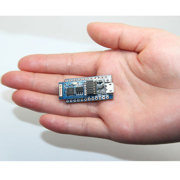
How to flash espduino firmware on Cactus Micro ESP8266 rev1
Posted by
Aaron
October 13, 2015
October 17, 2015
Leave a comment
on How to flash espduino firmware on Cactus Micro ESP8266 rev1